Morning guys – I hope you’re all well as usual, and thought that after five weeks it was time to show you what I’ve been up to, and also try to provide some wiring detail for anyone that might need it. Many thanks again for the kind remarks chaps; you know it’s always appreciated.

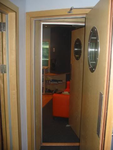
Firstly though, a view you haven’t seen in its finished state. Front lobby through to control room.
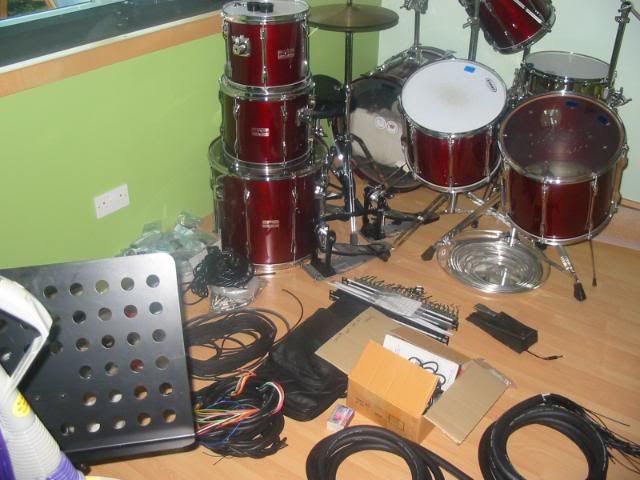
The live room was once again looking a total tip, but hey-ho, that’s progress apparently.

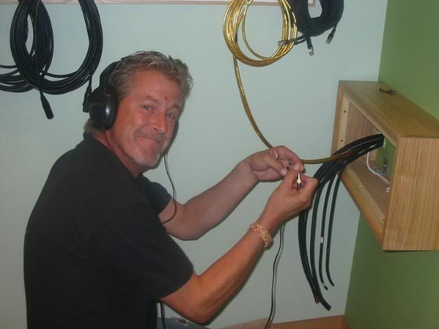
Right then Lou, remove one of Jeff’s panels behind the desk and start pulling those darn cables through.

The first lot weren’t too bad, but then I had to get a grown up to help me with the rest!

By taping them in a cone shape they eventually came through.
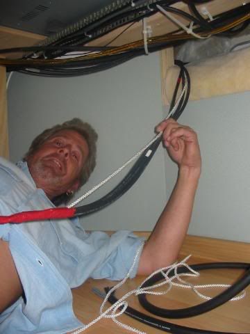
Those jacks of course need to be cut off and re-soldered once they’ve been threaded through the glands at the bottom right of the panel.
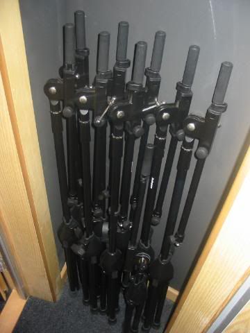
The small void between the front lobby and control room makes the perfect place to neatly store all the mic stands.
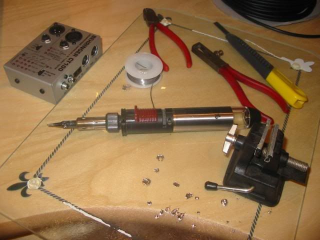
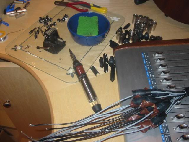
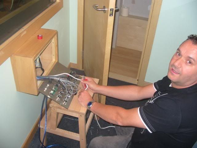
Then it was time to set up my soldering station.
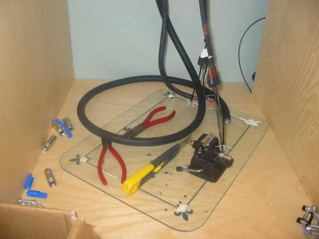
Before getting to work on pulling the cables to the iso booth.
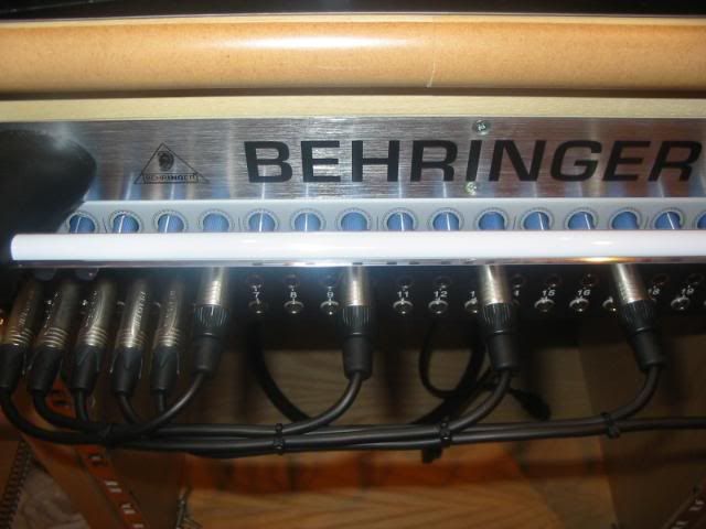
Now at this point I’d already made up and wired in all four of the assignable sends from the master desk to the two inputs on each headphone amp, (one for live room and front lobby, the other for the iso booth and eventually the conservatory). The next job was to connect balanced jacks to the other end of the headphone feeds coming from the live room panel, so that these could then be plugged into the rear of the top jack bay.
Then it was a simple case of patching some temporary patch leads from the bay to the individual inputs on the headphone amps.
It was done this way since whilst the presonus is a great sounding unit, its headphone level outputs are on the front panel. At this point it was time to do a crude test to check all connections thus far – They’re all fine! I simply stripped the other ends and held them against a headphone jack. I cannot emphasise enough the importance of checking all your connections wherever possible as you go – It makes it so much easier to diagnose a problem should it arise.
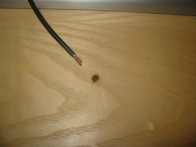
Now if you’re thinking that all this is going a little too smoothly, imagine my total horror when I realised that I’d stupidly put my high output gas iron on top of my workstation instead of the glass!

I was absolutely gutted, but Sarah came to the rescue as you’ll see in a moment.

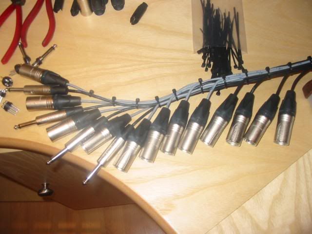
Now then for anyone who hasn’t wired up the back of a desk before this is how it’s done. Please bear in mind that in my situation (and I’m sure I’m not alone) I have virtually no access to the rear as the desks are so tight against the front wall, and there was no way they were coming out again. Firstly, pull through enough cable from the live room to enable you to work on it in the middle of the control room. Strip the 16 pair (in my case) back enough to cover the entire width of the desk you’re wiring to, hold all cores accross all chanels and accurately cut each one in numerical order, so that it lines up with its corresponding channel strip.
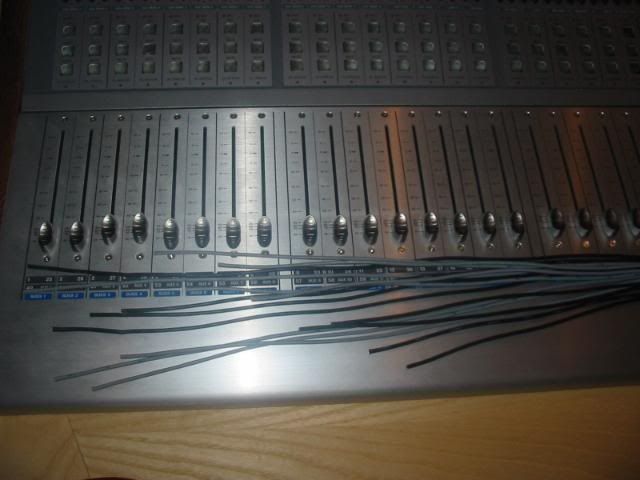
In this case the cable was fed from right to left, and so, cable 1 was the longest and cable 24 (part of the other 16 pair) the shortest. Then thread all plastic sleeves onto the cables and secure in place with tape. There’s nothing worse than soldering the perfect connector to later realise that you’ve forgotten to thread the sleeves!
PS – If you look to the right of the cable by the iron, you can see how Sarah sorted out my burn mark. Now it’s barely visible – Nail file!!!
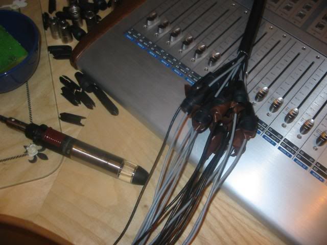
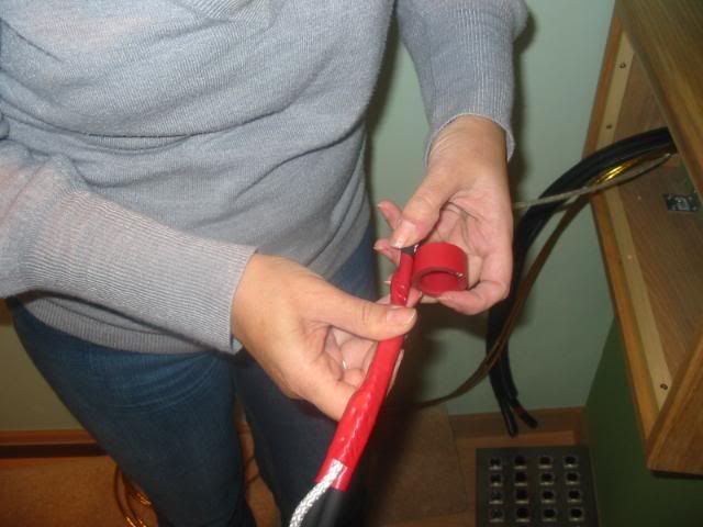
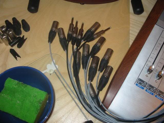
Prepare and ‘tin’ all cable ends and connector terminals.
Solder up the damn things.
And you’re done right?
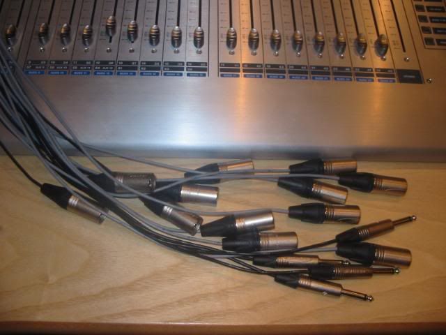
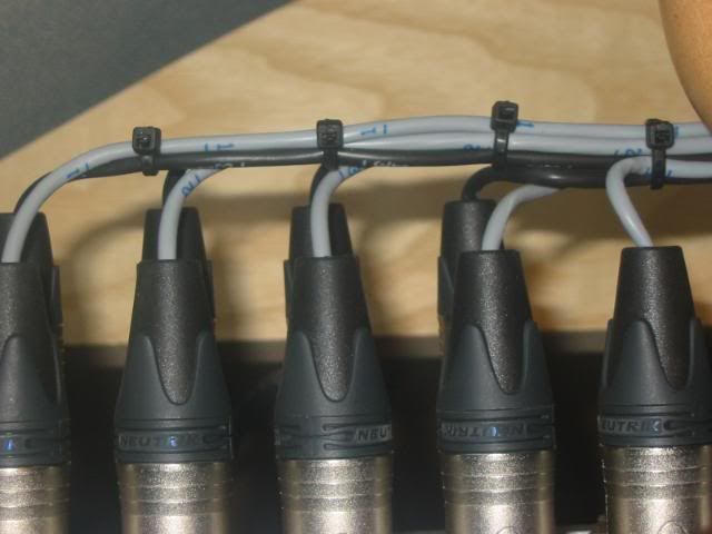
Wrong – Here’s the fiddly bit, but it’s well worth it. Lace all cables together 5cm from the connector to allow enough room for the bend into the socket on the rear of the desk. This is possible because of the accurate cuts made earlier, i.e., all cables are shorter than each other by the same amount.
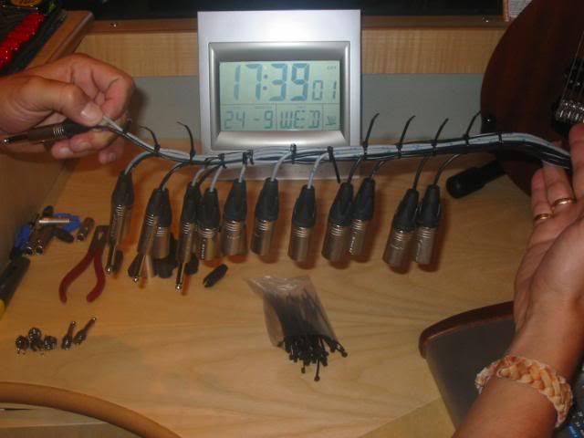
You can see where this is going now, and you can also see that the calendar is telling me I’ve got two days left! Finally tidy up to make things look the part.
The next step whilst insanely simple solves the access problem. Get someone to pull the 16 pair back through from the live room while you feed it from the control room, leaving enough showing to make the required connections. Very cramped, very awkward, but possible nonetheless. Top view.
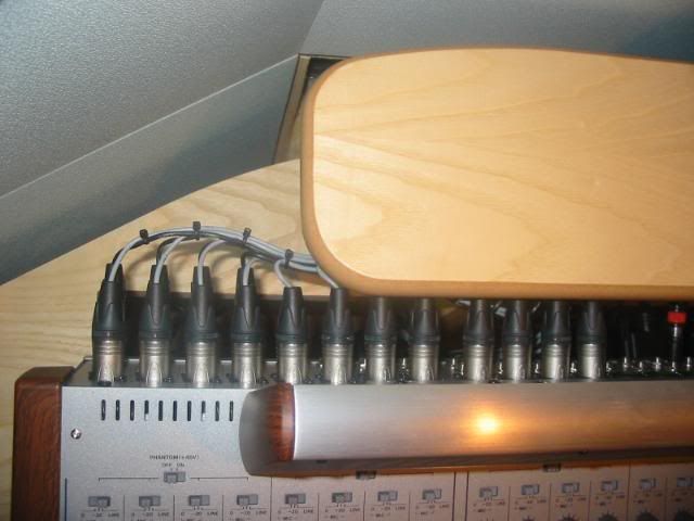
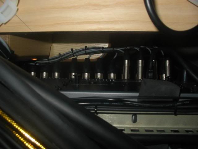
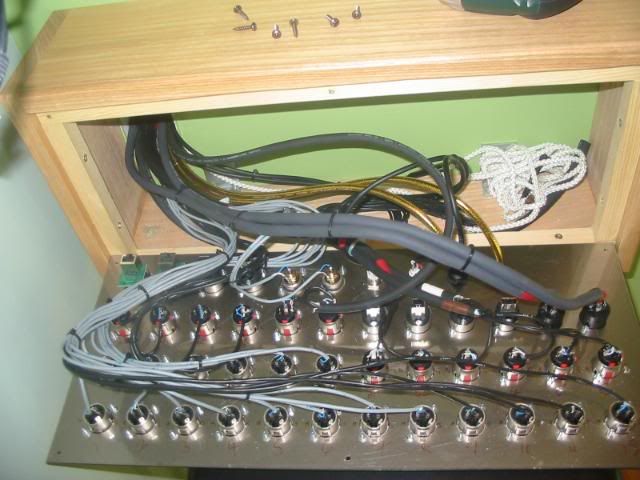
Bottom view, and you can see it’s starting to get crowded down here.
Then I cracked on with the custom loom to connect the jack bay to the headphone amp. Since this will always be visible to the outside world, extra care was taken re cutting and lacing.
Then it was on to the panels, first job is to number the back so that you don’t have to keep turning the panel over.
Once you’ve wired everything you need for the first session, replace the panels, and go for a beer. Try not to get too depressed in the pub when you think about the fact that they’ve both gotta come off again, and that you’ve not even started on the racks yet!
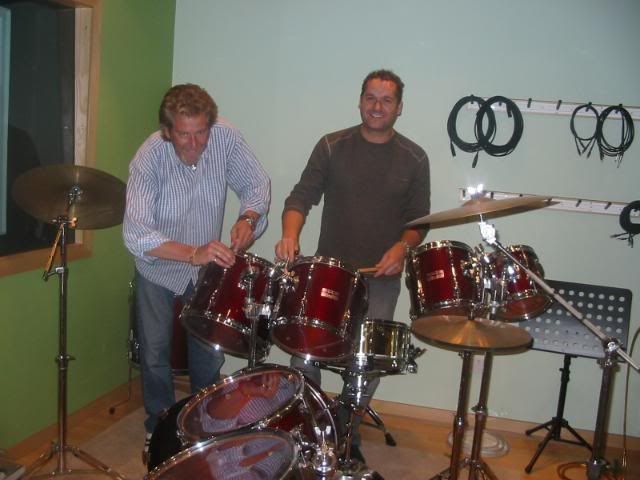
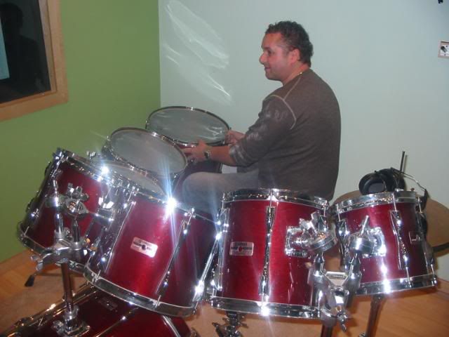
Introducing Andy – The guy who played drums on my album (awesome talent), and a part 17 certified electrician whose not bad with a soldering iron. He also kindly sourced my kit, so it was only fitting to get him to change and tune all my drum heads last Tuesday night!
Then first thing Wednesday the panels were off again and all remaining cables pulled through – that was really hard work.
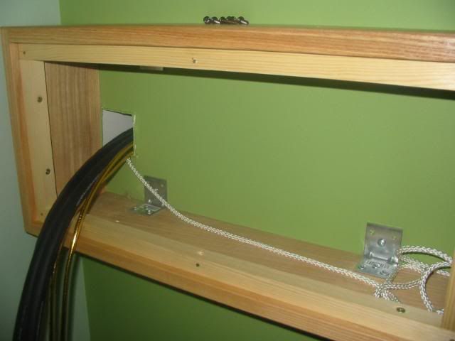
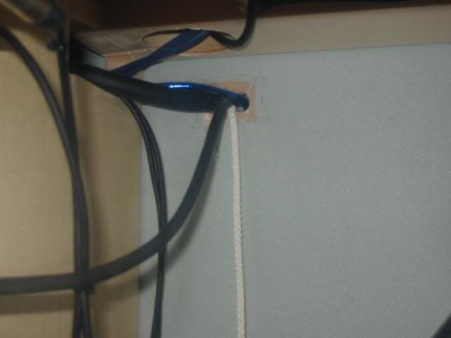
Everything is threaded through the large straps, which, if you recall are screwed with cable tie mounts to the underside of the workstation.
All cables now through both walls to both racks.

Get the radio on, and just ‘get in there dudes’
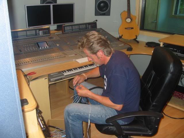
It was an exhausting couple of days, both physically and mentally – keeping a track of where everything was going, making sure Andy was remembering that pins 1 & 3 on an XLR plug appear to be reversed on an XLR socket etc etc. Then of course it was time to run all cables from the racks back to the desks. More ‘nerdy’ lacing then.
Lunchtime on Thursday and Studio 4’s live room panel is finished.
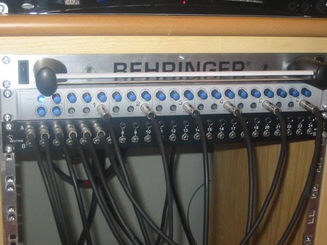
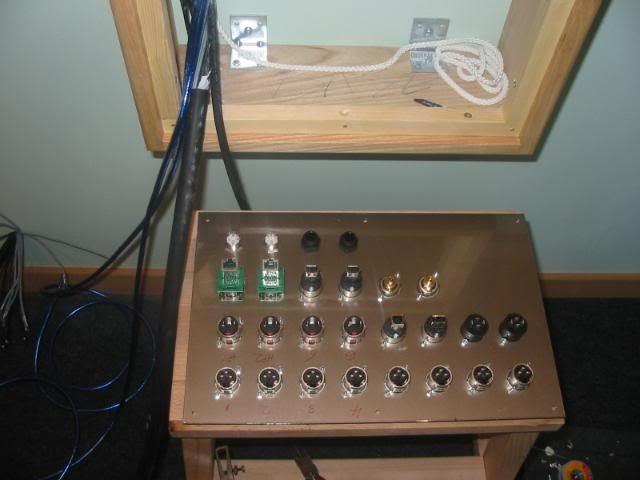
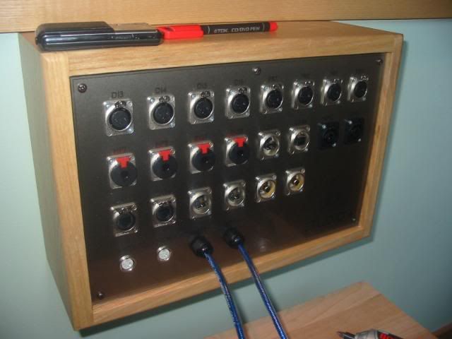
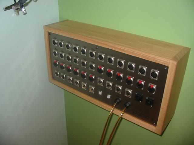
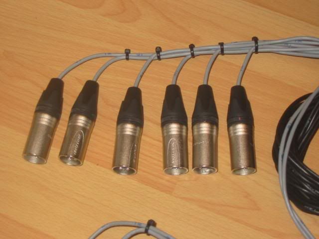
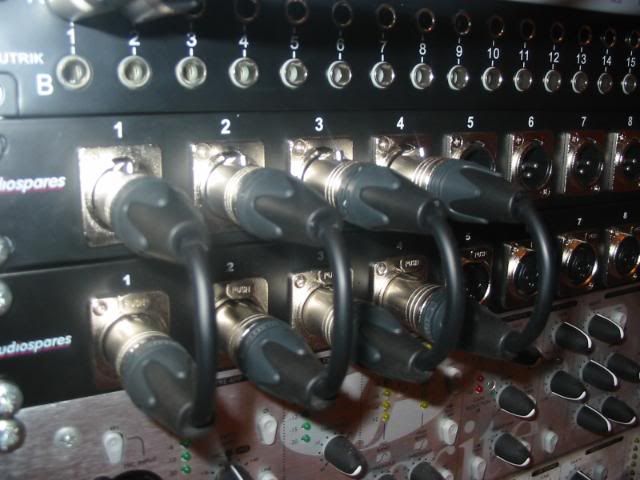
Snakes were wired up, laced and connected to the other desk as before and terminated to the patchbays. All I then had to do was make up more fully visible patch cords, only this time, with XLR’s. Once again (XLR) inputs to the Twintrack Pros are on the front panel. I enjoyed making these!
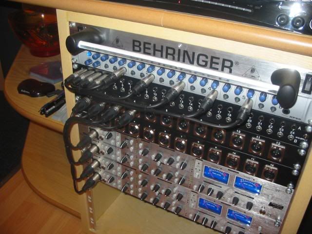
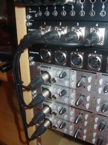
The Voice Masters inputs are on the rear panel, so I was able to use both male and female XLR patchbays.
And voila my friends – All done and dusted, with plenty of room for expansion if ever necessary.
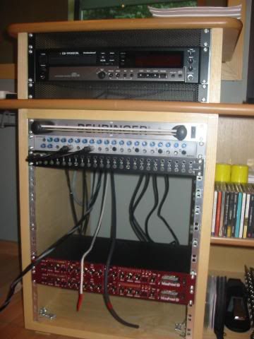
Left hand rack, the wiring for the X3 (in the top 3U) is already done and routed back to the master desk.
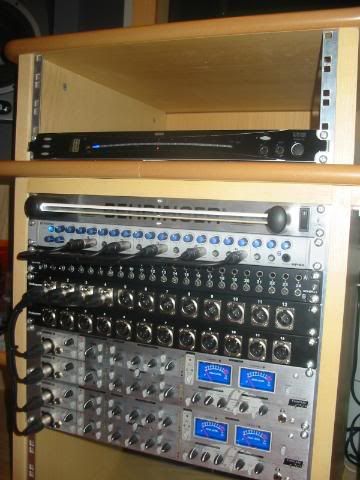
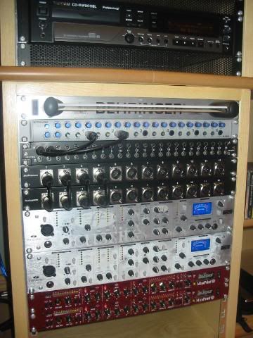
Right hand rack.
That’s it for this one my friends, other than to say that everything has been tested, it all works perfectly, and there are NO hums, buzzes or indeed any unwanted noises anywhere.
After exactly 15 months to the day since it’s start, Studio 4 is, as they say in the words of a certain ‘Cool Aussie’…………….UP!
The final bit is all the mics, a cupboard to put them in, and of course to eventually fit out the kitchenette and decorate the toilet. Also I must one day wire in the conservatory, but I don’t need it to earn for now. Work has been non stop in the middle of all this and looks set to continue that way for the foreseable future.
It’s been a hell of a ride, but I offer heartfelt gratitude to the forum, the community, and
all my new mates up here.
Take care dudes, final closing post to come, and the video walkthrough, promise!
Regards to you and yours as always,
Lou.

P.S. The session went like a dream btw - I'm getting the better of the gear at last!